Download the Lessonotes Mobile Liberia app for faster lesson access on Android and iPhone.
Subject: Physics
Semester: 2
Period: 4
Week: 21
School Name:
Teacher’s Name:
Subject: Physics
Grade Level: Grade 12
Week & Period: Week 21, Period IV
Date:
Main Topic: Alternating Current (AC) and Electronics
Sub-Topic: Resonance in RLC Circuits
Learning Objectives:
By the end of this lesson, learners should be able to:
- Define electrical resonance in an RLC series circuit.
- Derive and apply the formula for resonant frequency.
- Explain the conditions necessary for resonance.
- Analyze current behavior in resonance.
- Conduct and interpret a resonance experiment using function generators.
Instructional Materials:
- Function generator or variable-frequency AC source
- Resistor (R), Inductor (L), Capacitor (C)
- Voltmeter and Ammeter
- Oscilloscope (optional)
- Multimeter
- Wires and breadboard
Anticipatory Set (Warm-Up):
Pose this real-life scenario:
“Tuning a radio involves adjusting a knob to receive the clearest sound. What do you think is happening electrically inside the radio?”
Use this to introduce the idea of resonance — maximum response at a particular frequency.
Building Knowledge (Main Lesson):
- Definition of Resonance:
- In an RLC series circuit, resonance occurs when the inductive reactance equals the capacitive reactance:
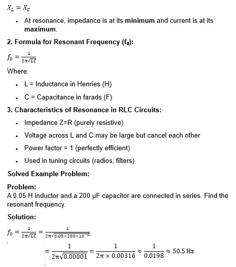
Experiment: Investigating Resonance in an RLC Circuit
Objective: To determine the resonant frequency in an RLC circuit.
Materials Needed:
- Function generator (10–100 Hz range)
- 100Ω resistor
- 0.05 H inductor
- 200 μF capacitor
- AC ammeter
- Voltmeter
- Connecting wires
- Breadboard
Procedure:
- Connect R, L, and C in series across a function generator.
- Set the frequency to 10 Hz and gradually increase it.
- Record the current at each frequency.
- Note the frequency at which the current is maximum — that is the resonant frequency.
Observation: The current increases to a peak at resonance and then decreases again.
Conclusion: At resonance, the impedance is minimum and the power transfer is maximum.
Activities and Guided Practice:
- Derive the resonance formula in small groups.
- Predict resonant frequency given different values of L and C.
- Use graph paper to plot current vs frequency — identify the resonance point.
Assessment:
Classwork:
- What is resonance in an RLC circuit?
- If L=0.1H and C=100 μF, calculate the resonant frequency.
- Sketch a graph of current vs frequency in a resonant RLC circuit.
Homework:
- A circuit resonates at 60 Hz. What happens if the frequency is changed to 80 Hz?
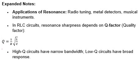
- Explain one application of electrical resonance in real life.
- Describe the energy transfer in an RLC circuit at resonance.
Differentiation:
- Use animations to show the variation of impedance with frequency.
- Let practical learners vary components and directly observe changes.
- Use analogies (e.g., child on a swing = resonance).
Teacher’s Reflection:
- Were learners able to observe resonance in real time?
- Did they connect theory with experimental results?
- What support do struggling learners need for calculations?